Saturday, February 27, 2016

Lego Racer

Task/Challenge:

Using a PicoCricket powered old rectangular motor, design a lego car carrying a 1.0kg weight over a 4 meter carpet course.  The old motor has a high speed but low torque, making it difficult for the vehicle to move with a kilogram of weight.

Torque/Speed:

Torque and speed are inversely proportional.  To move the kilogram weight, my partner, Thessaly, and I had to increase the torque and decrease the speed to create the perfect balance for a fast and effective vehicle.

Materials:

-     8 tooth gear, 16 tooth gear, 24 tooth gear, 40 tooth gear
-     6 wheels, 2 of each type
-     PicoCricket, Motor Board, Motor, cables to connect them
-     1 kg weight
-     Lego parts from the Lego cabinet


Day 1:

Without realizing that the high speed of the motor would be a problem, we created a car with only two gears, an 8 tooth and 40 tooth for maximum speed and minimum friction.  We connected the two gears with a chain without realizing the massive amount of friction it would contribute to our car.  When we connected the motor to our car, there was too much speed and not enough torque to spin the gears.


Day 2:

For the rest of our models, we realized the motor could power a gear train connected to a set of wheels like a two wheel drive.

Our second and third model was to create vehicle with a gear ratio of 3:5 using a 24 tooth and 40 tooth gear and a vehicle with a 1:5 gear ratio using an 8 tooth gear and 40 tooth gear.  Both those models needed higher torque as the car still would not budge with a kilogram weight.

We proceeded to a 1:25 gear ratio using two 8 tooth and 40 tooth gears to create a gear train.  Our vehicle took about 10 seconds to cover the 4 meter course.

For further improvement, we continued to increase the gear ratio to 3:125 by adding another 24 tooth and 40 tooth gear.  Our car took about 20 seconds to cover the 4 meter track.

Without thinking about reducing the gear ratio, we concluded 1:25 was the best gear ratio for the fastest car.

Then we realized our car was going the opposite direction of what we expected.  We tried adding another gear but keeping the same gear ratio but that created extra unneeded friction.

To the left is our final model with the weight and PickoCricket.


Calculations:

Gears Gear Ratio Speed(s)
one 24:40 --> (24/40) 3:5 0
one 8:40 --> (8/40) 1:5 0
two 8:40 --> (8/40)^2 1:25 10
two 8:40; one 24:40 --> (8/40)^2 * (24/40) 3:125 20

Here is our 1:25 gear ratio using two 8 tooth and two 40 tooth gears to create a gear train.  We connected an 8 tooth gear to the motor and the final 40 tooth gear to the axil of the wheels.  The wheels spin a factor of 25 times slower than the motor but has a torque 25 times as large.


Final Product:


Sunday, February 21, 2016

Windlass

Task:

Our second task was to design and build a windlass.  A windlass is a device generally used to haul or lift a bucket from a well.  Taking what we learned with the drill press, thermal press and arbor press in class, and SolidWorks from the bottle opener task, we are to expand and put together a windlass of our own invention.

Challenge:

My partner, Jenny, and I had to create a windlass able to crank 1 liter of water with 10 cm above the surface of the table.  The well is 12 cm in diameter and our windlass cannot use more than 500 cm^2 of delrin sheet.  In addition, we are allowed a 50 cm delrin rod and 120 cm of string.

Day 1 and 2: Brainstorming

Our ideas were jotted on paper, a model with a rectangular base and triangular supports with a crank and wheel system to pull up the water.

Design 1:

Our original design was to tilt the two triangular side supports in to create more of a pyramid, triangle shape before realizing the multiple obstacles we would face in order to create pegs and slots, and connecting delrin sheets with piano wire at a tilted angle.  Our original design also had a form of wheel and pulley system in between the two tilted triangular parts and a crank on the side of one of the supports to crank up the water.

Design 2:

However, we kept the triangular supports on the side but instead put them upright and would connect them with a support beam across from the bottom of one side to the top of the other for triangular rather than a square support.
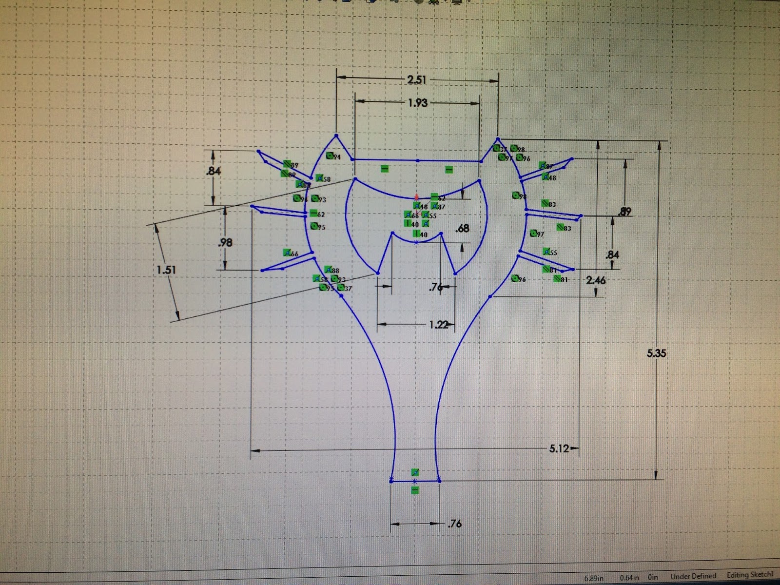


Measurements:


Top Left: triangular support piece 1
Top Center: general measurements for the triangular supports
Top Right: triangular support piece 2
Bottom Left: pegs and slots
Bottom Center: slanted support beams
Bottom Right: overall windlass 2D surface area measurements

Day 3: Building

Using SolidWorks, we created pieces for our windlass.  In order to save material and stay within the delrin limit, many parts were cut out.

Iteration 1:


Design 2 posed a problem with the crank attached to the side of a triangular support.  We moved it to go in between the supports.  However, with a crank, the crank would not turn unless on the outside of the side supports.  This forced us to move the pulley system to one side of our windlass in offer for our crank to work.

Initially, we wanted three delrin rods within the wheels for the string to wrap around, not including the middle piece, but we ran out.  In our first model, there is a long piece for the center, a medium piece for the crank, and a small piece for just the wheels.

After testing, our model failed.  The entire windlass was lopsided.  Slanted triangular supports, pulley off to one side, two rods for the wheel - they all contributed to an uneven windlass.


Day 4: Final Building and Testing

Design 3/Iteration 2:

To create a more balanced windlass, we put the wheel in the center of the windlass and created supports going across rather than diagonal.

With the already cut delrin rod, I took the medium sized rod and cut that in half to put three rods in between the wheels as initially planned.  I made a handle with delrin sheets but realized a one-finger approach was needed in order to crank it which posed not only difficult but also uncomfortable.

The wheels, our pulley system, was our cantilever.  With now three rods of shorter lengths for the string to wrap around, our cantilever was more reliable and was able to withstand more force.

After cutting the medium sized delrin rod in half, the original small sized delrin rod had an extra few centimeters to be cut off and connected to the other end of the handle for an easy crank.

However, with the large force and weight of the liter water, when cranking, the wheel and handle would spin in circles around the center delrin rod.  For an easy fix, Jenny and I used the drill press to drill a hole trough the delrin sheet and rod while inserting a piano wire to ensure the rod, wheels, and handle would move as a unit.

As a last minute touch, we added tight bushings to the rod and side triangular supports to reduce moving of the pulley while in use.

Here is a video of our final windlass model:


Obstacles:

While using the laser cutter to cut our pieces, the extreme heat and constant usage of the laser cutter created bending of the material.  This caused difficulties with precise measurements for pegs and slots and would create different cut lines.

The laser cutter was also very unpredictable with cutting.  Many times, our parts would not cut through resulting in more repeat cut lines, resulting in more bent material.

Further Improvements:

With more time, Jenny and I would reduce the material used by scaling the windlass down and use that excess material to create something to pin or clamp our windlass to the desk in order to use the windlass with one hand.  In addition, we would change the material to increase the Young's modulus so the rod in the middle would not bend due to extreme amounts of force.

Sunday, February 14, 2016

Mechanisms

Reciprocating Rectilinear Motion

How it works:  Reciprocating motion is a repetitive motion including gears that convert rotational motion to linear motion.  A pin is connected to a revolving disk in an "arm."  While the disk rotates, the pin rotates the arm which in turn is connected to a gear.  The gear is aligned with more teeth on a bar.  The rotating disk and arm produces a repetitive motion fostering the reciprocating motion.


Every time I see this mechanism in motion, I am awed by the rotation of the disk and how that translates to the bar at the bottom.  Rotational motion is converted to linear motion through a pin and an arm slot.  No matter how many times the disk rotates and the bar moves, the height from the center of the disk to the gear does not change.

Sunday, February 7, 2016

Fastening & Attaching

Task/Goal:

For our next assignment, I will need to learn how to connect Delrin pieces together using three different methods:

  • Piano Wire Fastening
  • Heat Stake
  • Peg and Slot

In addition to learning how to connect pieces of Delrin, we will be learning how to use the machines to perform those tasks:
  • Drill Press
  • Thermal Press
  • Arbor Press


Drill Press:


Piano Wire Fastening:  A drill press is used to drill a hole of a specified diameter into multiple Delrin pieces.  A piano wire can then be inserted into the hole to connect the pieces.

Benefits:  If done correctly, two pieces can click and lock in different positions.  For example:  two pieces in  a 90 degree angle or same two pieces in an 180 degree angle.

Drawbacks:  If not done correctly, pieces connected could be too loose or too close for pieces to turn and lock into position.

If I were to create a wheel that spins, I would use a piano wire to connect the two parts but would use a loose bushing so the wheel can spin without 
restrictions.  If I wanted the wheel in place to for 
example a wall, I would use a tight fit.


Thermal Press:

Heat Stake:  Two pieces of Delrin is put beneath the machine where heat will be applied and will melt the plastic.  The piece being melted will weld into a spherical shape until both pieces melt together.  

Benefits:  Thermal pressing is extremely quick and easy to use, while also producing a sturdy piece because it is permanent.

Drawbacks:  Because thermal pressing is permanent, once welded, there is no turning back.  If a mistake is made, all parts will need to be re-cut and the process must be done again.

If I were to connect corners in an easy fashion, I would choose to use the thermal press as it is quick and easy to use.

Arbor Press:

Peg and Slot:  Two Delrin pieces are connected like lego pieces, with pegs fitting in slots to create either a tight fit or loose fit.

Benefits:  If measured correctly, no extra materials other than the Delrin itself is needed.

Drawbacks:  Using the laser cutter to create pieces, there will be a margin of error after the laser cutter evaporates some of the Delrin material.  Very easy to get a fit too tight to put together or a fit too loose for any use.

If I were to connect two slanting pieces, I would use the drill press to create a slanted hole in the material but use the arbor press to correctly line the holes and insert the piano wire.

Tight Bushings vs. Loose Bushings:

Tight bushings are beneficial when making a sturdy structure.  For example making a box by connecting pieces using pegs and slots.  Tight bushings ensures a sturdier box.
Loose bushings are beneficial when 

When measuring the rods and bushings: 
  • loose bushings - 6.48 mm
  • medium bushings - 6.38 mm
  • tight bushings - 6.27 mm
  • rod diameter - 6.06 mm
The difference in millimeters between the loose bushing and the rod diameter is 0.42 while the difference in millimeters between the tight bushing and the rod diameter is 0.21.

When measuring the pegs and slots:
  • pegs - 0.2685 in
  • slot - 0.2770 in
The difference in inches is 0.0085.

When measuring the peg plate with labeled widths:
  • 0.135 in - 0.1400 in
  • 0.125 in - 0.1335 in
  • 0.115 in - 0.1150 in
The average change in distance was 0.00675 in.  This means while specific dimensions were put into SolidWorks, when the laser cutter was used, the laser evaporated an average of 0.00675 in of Delrin.  

Discrepancy:

When creating pegs and slots, I need to take into account the material that will be evaporated by the laser in order to create a perfect fit.  Otherwise, I may end up with a loose fit when I intended for a tight fit by using exact measurements to be cut.  The real part and the model may have extremely similar measurements, but the small change created by the laser cutter is big enough to change the tightness or loosness of a fit.

Bottle Opener

Task: 

Our first task was to create a bottle opener using a 3D Cad design software, SolidWorks, and the laser cutter while applying the engineering design process.  The engineering design process consists of seven steps that follows:
  • Research
  • Brainstorming
  • Selection
  • Analysis
  • Prototyping 
  • Experimentation/Evaluation
  • Redesign
These steps are to be done over and over again until the model is perfected.

Purpose:

The purpose of creating a bottle opener from scratch was not only to apply the engineering design process but also to learn about cantilevers and the deflection of when too much force is applied to the cantilever.

Limitations:  

  • The bottle opener may not be greater than 6" x 6" inches
  • The bottle opener may not twist-off the bottle cap
  • The material of the bottle opener needs to be made from a single sheet of polycarbonate

Day 1:

My partner Magnolia Pak and I began drawing out fresh ideas on paper.


The first few models were modeled off of wrenches.  

The model below had teeth to grip under the bottle cap which we believed would not have enough surface area to the bottle cap.


The top left model was designed as the hole in the middle therefore needing to use three hands: two holding the bottle opener one holding the bottle.  We discarded the idea as complicated.


The next few models were designed to have a ledge under the bottle cap while pushing down on the handle bar lifting the bottle cap off the bottle.


With this model on the right my partner and I changed the handle to be thicker near the cap opener with the fear of snapping the handle due to too much force applied on the handle.  We also added finger indents for an easier grasp of the handle.  This became our first permanent idea.


Above, we removed the outside ring believing it was unnecessary.

With the phrases "embrace all ideas" and "defer judgment," Magnolia drew a bottle opener we later decided too complicated for a simple purpose.


While debating the look of Bottle Opener #6 in my dorm room later that night, I concluded the outside ring was completely useless.  But by curving it down, the top of the ring could act as a pressure pushing down on the middle of the bottle cap while the bottom digs under the cap and pushes the cap up.

This model became the model our first laser cut prototype.


Instead of the top of the ring pushing down on the bottle cap, we explored the idea of the sides pushing down on the bottle cap for more surface area.  We later concluded that might not benefit us.


Day 2:

My partner and I met in the engineering lab to cut out our second permanent bottle opener, Bottle Opener # 9.  The picture below are the two foam core models we created from Bottle Opener #6 and Bottle Opener #9.


Day 3:

Using SolidWorks, my partner and I designed a 3D model of our bottle opener.  Below is our first laser cut model.  While designing and sketching in SolidWorks, we skipped curving edges for a more rounded design and changed the look of the handle to avoid a magnifying glass look.


Day 4:

We decided to curve the part of the bottle opener where it will be touching the bottom of the bottle cap for more surface area.  There is no picture available but the curve was too tight and we decided to make a third model with a wider curve.

Day 5:

Our third and final model came with a cat design as our fun side project.


Here is our model in SolidWorks, with the multiple dimensions ensuring perfect fit around the bottle cap and for the correct 6" x 6" length.

The picture to the right is our third and final model.
In SolidWorks sketch, we drew eyes at the top and the word "meow" adding whiskers and a collar and bell beneath.  With difficult lighting, we could not capture a picture clearly showing the engravings.


Idea of the Bottle Opener:

With part of the bottle opener under the cap as a leverage and another on the top of the cap, we would use our thumb to push down on the mouth of the opener and the bottle opener would act as a lever, with our hand applying the force.

Further Improvements:

If our product were to be mass manufactured, I would widen the curve that fits under the bottle cap.  When we measured the diameter, Magnolia and I did not take into account the angle of which we would angle the bottle cap opener to fit under the bottle cap.  By widening the curve, it would ensure a more secure and easy fit.  We would also change the material to be metal or stainless steel for less chipping and less stress applied to the material while using the bottle opener.